Difference between revisions of "BLIP DSL"
(→endevent) |
(→callActivity) |
||
| Line 255: | Line 255: | ||
=== callActivity === | === callActivity === | ||
| − | With the keyword '''callActivity ''' followed by a qualified name and combined with the keyword '''for''' followed by its given ''id'' defined in the <code>.bpmn2</code> model file, you can respectively define a [Call Activity] and match it to its corresponding graphical representation. | + | With the keyword '''callActivity''' followed by a qualified name and combined with the keyword '''for''' followed by its given ''id'' defined in the <code>.bpmn2</code> model file, you can respectively define a [Call Activity] and match it to its corresponding graphical representation. |
► '''Syntax''': | ► '''Syntax''': | ||
<syntaxhighlight lang="java"> | <syntaxhighlight lang="java"> | ||
| − | + | callActivity <callActivity name> for <callActivity_element> | |
[onentry <functionlibrary_function_name>] [onexit <functionlibrary_function_name>] | [onentry <functionlibrary_function_name>] [onexit <functionlibrary_function_name>] | ||
</syntaxhighlight> | </syntaxhighlight> | ||
| Line 265: | Line 265: | ||
► '''Example''': | ► '''Example''': | ||
<syntaxhighlight lang="java"> | <syntaxhighlight lang="java"> | ||
| − | + | callActivity ProductMaintenanceMany for CallActivity_1 onentry workOnManyProductsOnEntry onexit workOnManyProductsOnExit | |
</syntaxhighlight> | </syntaxhighlight> | ||
Revision as of 12:05, 8 December 2017
Contents
Purpose
The Business Logic Implementation Process (or BLIP) DSL provides you with all the components you need to design and implement business processes. Those components are based on the current Business Process Management and Notation (BPMN 2.0) specification and rely on this standard.
In order to use the BLIP DSL, you should have a basic and broad understanding of the business processing management filed. Hence, you will find the all the basic information you need to understand, what you can achieve by designing your processes first (step1 – flowchart as process diagram), then implementing and so forth cementing the logic behind it, using the BLIP DSL Model (step 2).
BPMN2 Model Files
The graphical model of your business processes have to be done and saved in .bpmn2 files. Those contains flowchart visualizing each steps of a process. Those files can be created and modified using the functionalities provided by the jBPM Framework.
Designing a simple process diagram with jBMN
You have to model some OS.bee specifications using the Eclipse Properties View. Create a new BPMN2 process with “New - BPMN2 - jBPM Process Diagram” and remove the prefix defaultPackage. from Process ID.
A process diagram can contain some of the following components:
- Start Event: models exactly one Start Event or the start of the process itself.
- End Event: if the process should be used as a sub process for Call Activities, model exactly one End Event; otherwise model at least one End Event
- Script Task: models function library calls, which should execute immediate
- Service Task: model web service - which has to be investigated further - and function library calls, which should execute mostly asynchron or fire-n-forget tasks.
- User Task: model a UI based task
- Reusable Process / Call Activity: call another modelled process in here
- Gateways:
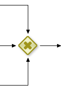
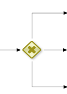
- Data-based Exclusive (XOR) - Converging - one of many sequence flows will be triggered; always pair a Converging gateway with a corresponding Diverging
- Parallel (AND) - all of the sequence flows will be triggered; always pair a Converging gateway with a corresponding Diverging
- Inclusive (OR) - Converging - any (at least one) of many sequence flows will be triggered; Converging OR gateways are not supported!
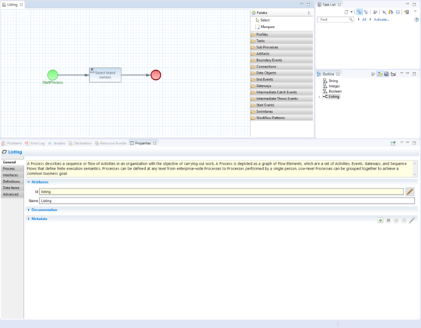
Following examples illustrate how the entry of person’s data or an inventory process could be designed using in both cases one Start Event, one User Task and one End Event; resulting in the creation of both files DataEnty.bpmn2 and Inventory.bpmn2.
► Example 1: DataEnty.bpmn2
► Example 2: Inventory.bpmn2
After you’re done designing your business process the second step is to define and implement the business logic to support it: what has to happen at the beginning, during and at the end of the process itself. This part is taken over by the BLIP DSL Model.
BLIP Model Files
The BLIP DSL model provides you with the standards elements needed for you to implement the definitions of each steps of your business processes. All processes (blips) are defined in text files with the file extension .blip.
BLIP DSL model files are made up of the following sections:
- Package declaration: The message model file must have a unique fully qualified name that can be specified with the keyword package at the beginning of the file.
- Process section: The process section contains all the process declarations and definitions (blips): it is the list of all defined and available processes.
package
With the keyword package followed by a unique qualified name, you define the root element of the model that contains all the other elements. A model can contain multiple packages.
► Syntax:
package <package name> {
    process <process name> [describedBy   “process description”] [workload using dto <dto-name>] [icon <icon-option>][image <image name>][logging][functiongroup <rule-id>]
    bpmn <process name> (bpmn2 file name) { process steps definitions }

    process <one process name>     ... { process steps definitions }
    process <another process name> ... { process steps definitions }
}
► Example:
package net.osbee.sample.foodmart.blips { ... }
process
With the keyword process followed by an identifier name, you define a process unit in the BLIP DSL model, in which you can set the order of each step of the process, describe them, and match them with the graphical representation of the process in the designed BPMN2 file.
► Syntax:
package <package name> {

    process <process name> [describedBy   “process description”] [workload using dto <dto-name>] [icon <icon-option>] [image <image name>] [logging] [functiongroup <rule-id>]
    bpmn    <process name> (bpmn2 file name) { process steps definitions }

    process <one process name> ... { process steps definitions }
    process <another process name> ...
}
icon
The currently available icon options are the following:
- arrow-cw | *attach
- attention
- back
- bell
- block
- calendar
- camera
- cancel | cancel-1 | cancel-circle
- chart
- chart-pie
- clock
- cog
- comment
- cw
- doc
- down | down-bold | down-dir | down-open | down-thin
- download
- edit
- exchange
- export
- eye
- flag
- folder
- forward
- heart | heart-empty
- help | help-circle
- home | home-1
- info | info-circle
- left | left-bold | left-dir | left-open | left-thin
- link
- location
- lock | lock-open
- minus | minus-circle
- mobile
- monitor
- music
- ok
- pencil
- plus | plus-circle
- reply
- resize-full | resize-small
- retweet
- right | right-bold | right-dir | right-open | right-thin
- search-1
- start | start-empty
- tag
- th | th-list
- trash
- up | up-bold | up-dir | up-open | up-thin
- upload | upload-cloud
- user | user-add
- users
- vcard
Further informationsn will shortly be provided.
► Example:
package net.osbee.sample.foodmart.blips {
    process listing icon chart describedBy "Listing of POD items" workload using dto MproductDto bpmn listing  {
        startevent StartProcess for StartEvent_1
        usertask SelectBrandOwners for UserTask_1
        endevent sdf for EndEvent_1 ends token path
    }
}
describedBy
With the optional keyword describedBy you are able to add a description of the process unit.
► Syntax:
package <package name> {
    process <process name> [describedBy   “process description”] ... {}
}
► Example:
package net.osbee.sample.foodmart.blips {
    process listing describedBy   "Listing of POD Items" ... { ... }
    process ProductMaintenance describedBy "Product Maintenace" ... { ... }
}
logging
With the optional keyword logging ...
workload
With the optional keyword workload ...
functiongroup
With the keyword functiongroup ...
bpmn
With the keyword bpmn followed by its given id name in the corresponding BPMN2 file name, you can specify and bind (match) the underlining designed business process.
Process Step Definition
After the successfull match of the .bpmn2 model file (nor errors in the IDE) and the process unit itself in the BLIP DSL model, you can describe each steps of the process using the BLIP-Notation mentioned above using the set of keywords described in this section.
- onentry <functionlibrary_function_name> defines which function has to be executed at the beginning of the selected task or event.
- onexit <functionlibrary_function_name> defines which function has to be executed at the end of the selected task or event.
startevent
With the keyword startevent followed by a qualified name and combined with the keyword for followed by its given id defined in the .bpmn2 model file, you can respectively define a [Start Event] and match it to its corresponding graphical representation.
► Example:
process listing icon chart describedBy "Listing of POD items" workload using dto MproductDto bpmn listing  {
    startevent StartProcess for StartEvent_1
    ...
}
endevent
With the keyword endevent followed by a qualified name and combined with the keyword for followed by its given id defined in the .bpmn2 model file, you can respectively define a End Event and match it to its corresponding graphical representation.
► Syntax:
endevent <endevent name> for <endevent_element> {ends token path | terminates process}
► Example:
process listing icon chart describedBy "Listing of POD items" workload using dto MproductDto bpmn listing  {
    startevent StartProcess for StartEvent_1
    ...
    endevent sdf for EndEvent_1 ends token path
}
callActivity
With the keyword callActivity followed by a qualified name and combined with the keyword for followed by its given id defined in the .bpmn2 model file, you can respectively define a [Call Activity] and match it to its corresponding graphical representation.
► Syntax:
callActivity <callActivity name> for <callActivity_element>
[onentry <functionlibrary_function_name>] [onexit <functionlibrary_function_name>]
► Example:
callActivity ProductMaintenanceMany for CallActivity_1 onentry workOnManyProductsOnEntry onexit workOnManyProductsOnExit
exclusivesplitgateway
With the keyword exclusivesplitgateway followed by a qualified name and combined with the keyword for followed by its given id defined in the .bpmn2 model file, you can respectively define a [Diverging Gateway] (exclusivesplitgateway XOR???) and match it to its corresponding graphical representation.
► Syntax:
'''exclusivesplitgateway ''' <exclusivesplitgateway name> '''for''' <exclusivesplitgateway_element>   {
{'''case'''|'''default'''} <case_name> '''for''' <sequenceFlow_element> when <functionlibrary_testname>}
Please note that the use of when is only allowed for case description, which allows you to define which test has to be executed.
► Example:
exclusivesplitgateway HowManyHaveBeenSelected for ExclusiveGateway_1 {
case None for SequenceFlow_12 when noProductsSelected
case OnlyONE for SequenceFlow_7 when oneProductSelected
default MANY for SequenceFlow_2
}
inclusivesplitgateway
With the keyword inclusivesplitgateway followed by a qualified name and combined with the keyword for followed by its given id defined in the .bpmn2 model file, you can respectively define a [Converging Gateway] (inclusivesplitgateway) and match it to its corresponding graphical representation.
► Syntax:
'''inclusivesplitgateway''' <inclusivesplitgateway name> '''for''' <inclusivesplitgateway_element>   {
{'''case'''} <case_name> '''for''' <sequenceFlow_element> [when <functionlibrary_testname>]}
► Example:
exclusivesplitgateway HowManyHaveBeenSelected for ExclusiveGateway_1 {
case None for SequenceFlow_12 when noProductsSelected
case OnlyONE for SequenceFlow_7 when oneProductSelected
default MANY for SequenceFlow_2
}
persisttask
With the keyword persisttask followed by a qualified name and combined with the keyword for followed by its given id defined in the .bpmn2 model file, you can respectively define a [Persistence Task???] and match it to its corresponding graphical representation.
scripttask
With the keyword scripttask followed by a qualified name and combined with the keyword for followed by its given id defined in the .bpmn2 model file, you can respectively define a [Script Task] and match it to its corresponding graphical representation.
► Syntax:
'''scripttask ''' <scripttask name> '''for''' <scripttask_element> function <functionlibrary_function_name>
► Example:
scripttask OneSelected for ScriptTask_3 function oneSelectedScript
usertask
With the keyword usertask followed by a qualified name and combined with the keyword for followed by its given id defined in the .bpmn2 model file, you can respectively define a [User Task] and match it to its corresponding graphical representation.
► Syntax:
'''usertask''' <usertask name> '''for''' <user_task_element>
[operatesOn <dto_name>]  [onentry <functionlibrary_function_name>] [onexit <functionlibrary_function_name>]
- operatesOn <dto_name> defines the underlying DTO object (or attribute), on which the selected user task changes have to be applied on.
servicetask
With the keyword servicetask followed by a qualified name and combined with the keyword for followed by its given id defined in the .bpmn2 model file, you can respectively define a [Service Task] (Web Service) and match it to its corresponding graphical representation.
► Syntax:
'''servicetask ''' <servicetask name> '''for''' <servicetask_element>
[operatesOn <dto_name>]  [onentry <functionlibrary_function_name>]
[run {oneway | asynchron | synchron} as {function | webservice} <functionlibrary_function_name>] [onexit <functionlibrary_function_name>]
► Example:
process SampleCallService workload using dto ProductWorkLoadDto functiongroup SampleCallService bpmn SampleCallService {

scripttask PreCallService for ScriptTask_1 function preCallService
servicetask ServiceFireAndForget for ServiceTask_1 onentry callFireAndForgetEnter run oneway as function serviceTaskFireAndForgetFunction onexit callFireAndForgetExit
servicetask ServiceAsynchron for ServiceTask_2 onentry callAsynchronEnter run asynchron 30 secsTimeout as function serviceTaskAsynchronFunction onexit callAsynchronExit
servicetask ServiceSynchronized for ServiceTask_3 onentry callSynchronizedEnter run synchron as function serviceTaskSynchronizedFunction onexit callSynchronizedExit
scripttask PostCallService for ScriptTask_2 function postCallService
}
Best Practices and More
Model the Functions for the Blip
- use blip-group function groups to enable the blip support provided
- always use only Object kcontext as the single parameter for every blip group function, test, rate
- use blip-group test for Gateway Sequence Flows
Model the Blip for the BPM
- reference any blip to one BPM
- each blip has to reference to - maybe its own - blip-group in the function library - each blip has to reference to - maybe its own - workload dto modelled in dto
- reference any blip user task to one BPM User Task
- the operative dto is either the workload dto itself defined in blip or any child dto - the corresponding perspective is connected inside perspective via blip - the optional on entry and on exit function library calls are modelled via blip
- reference any blip script task to one BPM Script Task
- the function library call is modelled via blip
- reference any blip service task to one BPM Service Task
- the service task can be implemented via
+a function library call modelled via blip +a web service call modelled via blip - which has to be investigated further
- both can be started
+synchronized - both on process and on technical level the bpm engine waits until the service task ends +asynchron with a timeout - on process level the bpm engine waits until the service task ends, on technical level a parallel thread is created +oneway - the service task is started wihtout waiting on its termination or results, the process will immediatly continue with the next node
- reference any blip call activity to one BPM Call Activity
- the optional on entry and on exit function library calls are modelled via blip
- reference any blip exclusive split gateway to one BPM Exclusive Gateways / XOR Diverging
- the sequence flow constraints are defined via blip using test functions - the order of the constraints are checked in the given order until the first positive check was found -the last constraint has to be default
- reference any blip inclusive split gateway to one BPM Exclusive Gateways / OR Diverging
- the sequence flow constraints are defined via blip using test functions - it has to be manually verified, that at least one constraint will be tested positive!
- reference any blip end event to one BPM End Event
- set the end handling either to terminate process or end active token path - see for https://docs.jboss.org/jbpm/v5.4/userguide/ch.core-basics.html#d0e1465
Model the Perspective for the Blip
- reference some perspective to one blip user task
Model the Menu for the Blip
- reference some menu entry process to one blip process to enable starting that process via user menu
Model the Authorization for the Blip
- define on role level, which blip process
- is startable - which user task is executable
Dos and Don'ts
- You must not copy & paste nodes (tasks, gatesways, etc), because internal BPM attributes seem to get corrupted.
- You can't and must not mix Diverging and Converging Gateways into one Gateway.
- Please be aware, that the Eclipse built in BPM editor doesn't support context sensitive support.
- Scripts should be immediate. They are using the engine thread to execute the script. Scripts that could take some time to execute should probably be modeled as an asynchronous Service Task. [...] avoid contacting external services through a script node. [...] should not throw exceptions.
- You must only use exclusive and parallel gateways. We recommend you to read "ISBN:9783446424555, Praxishandbuch BPMN 2.0 - 2.3.3 Datenbasiertes inklusives Gateway" for the discussion, how inclusive gateways can easily lead to un-checkable and un-implementable processes due to multiple and parallel token sequence flows.
- If you want to use inclusive gateways, you may need to use different end events, which will only end the actual token path.
Copyright Notice
All rights are reserved by Compex Systemhaus GmbH. In particular, duplications, translations, microfilming, saving and processing in electronic systems are protected by copyright. Use of this manual is only authorized with the permission of Compex Systemhaus GmbH. Infringements of the law shall be punished in accordance with civil and penal laws. We have taken utmost care in putting together texts and images. Nevertheless, the possibility of errors cannot be completely ruled out. The Figures and information in this manual are only given as approximations unless expressly indicated as binding. Amendments to the manual due to amendments to the standard software remain reserved. Please note that the latest amendments to the manual can be accessed through our helpdesk at any time. The contractually agreed regulations of the licensing and maintenance of the standard software shall apply with regard to liability for any errors in the documentation. Guarantees, particularly guarantees of quality or durability can only be assumed for the manual insofar as its quality or durability are expressly stipulated as guaranteed. If you would like to make a suggestion, the Compex Team would be very pleased to hear from you.
(c) 2016-2026 Compex Systemhaus GmbH


